Controlling rotation in a polar array in Autodesk Inventor
By John Hackney, IMAGINiT Technologies
CAD/CAM/CAE AutoDesk Inventor CAD Imaginit Technologies Inventor John HackneyHow to create circular patterns without the automatic rotation of the feature in Autodesk Inventor.
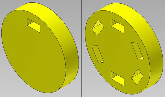
I often hear Inventor users say they are disappointed that during the creation of a circular pattern, they cannot prevent the feature from being rotated as it is patterned. This is true if you use the standard Circular Pattern tool as shown in the model below. The first image is of the part and the rectangular feature that will be patterned. The second image is the result of using the Inventor Circular Pattern tool and a fitted 6 placement feature.
There is no option to prevent the rotation of the feature during this operation. There is another method to get the same pattern but not have the feature rotate. It involves a little extra work but is not difficult to preform.
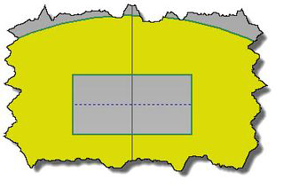
First, we create a sketch on the face of the part containing the rectangular slot. In this case, I sketched a construction line between the midpoints of the rectangular cutout to establish a point in the center of the rectangle. Your feature may require a different sketching method to achieve the desired pattern point.
Next, I sketched a circle that will be the path of the rectangular pattern. Notice the circle diameter is coincident with the midpoint of the construction line.
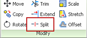
The next step is to split the circle into an arc. You cannot create a rectangular pattern using a continuous path; it must have a beginning and an end. You will use the Inventor Split tool to break the circle into an arc without removing any circumference length.
Select the Split tool and pick on the circle at the point it touches the construction line. A small red “X” will appear to indicate the split location. If others “Xs” appear that is OK just select the one indicated.
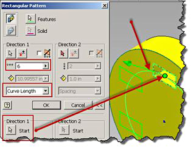
Finish the sketch and select the Rectangular Pattern tool. I selected the rectangular feature and then select the Direction 1 button in the dialog box. Select a point on the arc as indicated by the arrow. The point must be near the beginning of the arc. An green arrow will appear indicating your success. Enter the number of feature instances you desire and then select “Curve Length” for the pattern distance. Last you will need to select the Direction 1 Start button and pick the point indicated by the arrow. Select OK to finish.
You now have the desired pattern. The pattern behaves the same way other patterns do, and you can suppress any instance(s) except the original feature.
This article originally appeared on IMAGINiT’s Manufacturing blog.
 John Hackney is a mechanical application engineer at Imaginit Technologies with 25 years experience in the manufacturing industries including converting machinery, high speed pick and place, packaging machinery, and waste incineration equipment. He has served as CAD manager, designer, quality control checker, and engineering manager. He has also taught both secondary and community college level courses, including Industrial Technology, Drafting and Design and various CAD applications.


